
Shower Fan Wiring Diagram Artled
1 Tools & Safety Tips Preparation is essential to having a successful wiring project. Wiring a new ceiling fan requires a few basic tools: Screwdriver Wire strippers Electrical tape Voltage tester Ladder Pliers or needle-nose pliers Wire connectors Stay safe when doing any project that requires electricity: Use eye protection and rubber gloves.

The World Through Electricity How to wire a ceiling fan
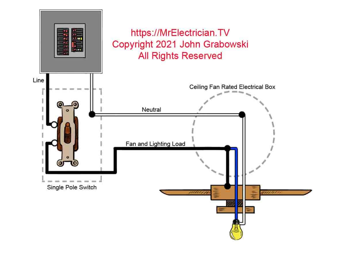
In this ceiling fan wiring diagram, the blue wire on the ceiling fan is connected to the LOAD side of the wall switch to control the fan's light. The black fan wire is connected to the LINE enabling the pull chain switch on the fan to control the fan motor independently of the wall switch.

Secret Diagram Popular Wiring diagram for harbor breeze ceiling fan
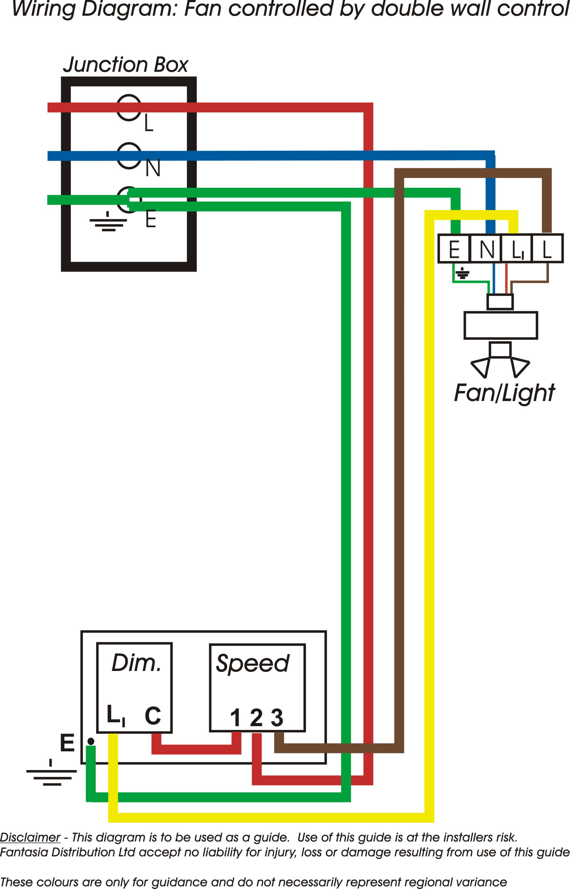
This page provides downloads of wiring diagrams for the most common methods of installing Fantasia Fans. Fan and Light by Pull Switch Fan Only by Pull Switch Remote Control Wall Control Wall Control Fan & Light Wall Switch Fan & Pull Cord Light Wall Switch Light & Pull Cord Fan Fan & Light Sharing Switch Supply

Wiring Diagram Of Electric Fan Wiring Saum Hadi Wiring Diagram
An electric fan wiring diagram is a schematic representation of how the components of an electric fan are connected and interact with each other. It provides a visual guide for proper installation and understanding of the electrical circuitry in the fan. In a standard electric fan wiring diagram, several components are typically included.
Fan Wiring Diagram Wiring Diagram
Guidelines for using the following wiring diagrams. Switch off the mains electricity supply before attempting any sort of fan installation or maintenance. All of these diagrams are meant to be used as guides only. Use of these diagrams is at the installers' risk. Fantasia Distribution Ltd accept no liability for injury, loss or damage resulting.

Ceiling Fan Wiring Diagram with Capacitor, Fan Regulator ETechnoG
1 Introduction 2 Basic requirements 3 Wiring plans 3.1 Basic fans 3.2 Fans with a timer 3.3 Fans with a built in humidistat 3.4 Fans with timer and humidistat 3.5 Using relay controls 4 Fused Fan supplies 4.1 With a fused fan isolator 4.2 With a new junction box 4.3 Using the existing ceiling rose 4.3.1 Simplified Schematic Version 5 See Also
Emerson Fan Motor Wiring Diagram Search Best 4K Wallpapers
To control a ceiling fan through remote, follow the following wiring instructions: First of all, turn off the main breaker to disconnect the power supply. Now connect the green / yellow wire to the ground wire from the household DB board. There are three outgoing and two incoming wires in the receiver.

Dual Fan Relay Wiring Diagram Database
Strip the ends of the wires. To connect your wires, the copper ends must be exposed. Remove the plastic caps that are on the ends of your wires. Use a stepladder to reach the wires in your ceiling and carefully cut away the plastic coating about 2 inches (5.1 cm) from the end of the wires with a wire cutter.

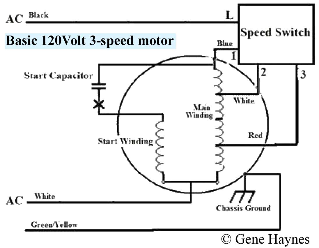
3 Speed Fan Wiring Diagram
Know it All about Ceiling Fan Wiring Diagram In this article 01 What is a Ceiling Fan? 02 How does a Ceiling Fan Work? 03 Ceiling Fan Wiring Diagrams 04 Use EdrawMax for Wiring Diagram Creation What is a Ceiling Fan? The ceiling fan is the best mechanical invention that makes people cool physically. It was invented in late 1800.

Pin Wiring Diagram Exhaust Fan Exhaust Cutout / Power Windows Wiring
This article aims to demystify stand fan wiring diagrams and provide a comprehensive breakdown of what they entail. To begin, a wiring diagram is simply a visual representation of a fan's internal electrical system. It consists of three components - a power source, a motor, and various switches and wires. The power source typically provides.
Fan Wiring Diagram Wiring Diagram
The four methods are: Powered ceiling fan and/or light without any switches (no switches) Switching the light and using the pull chain for the fan (Single switch) Using the same switch for switching both the light and fan (Single switch) Switching the light and fan from separate switches (Two switches)

50 Awesome 2 Speed Fan Wiring Diagram Electric cooling fan, Electric
Wiring diagram electric fan basic tutorial Teddy diy channel 82.7K subscribers Subscribe Subscribed 1.6K Share 159K views 3 years ago #wiringdiagram #electricfan #diy This is only a simple guide.
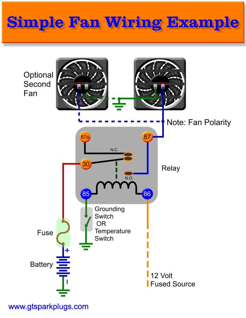
Automotive Electric Fans GTSparkplugs
Help An extractor fan is an essential part of any bathroom as it helps to remove the excess moist and humid air produced by the shower and keep any condensation build up to a minimum. In this guide we take a look at how a timed fan unit or extractor fan with a built in timer is wired up, read on to find out exactly how.

Ceiling Fan Wiring Diagram 1
Wiring with One Switch for Combined Control. Follow these steps if wiring with a single switch for controlling both the fan and light together: Bring the power supply cable and the cable from the fan to the switch.; Connect the fan cable's two hot wires using a wire cap and a 3rd small piece to connect to the switch. And the fan's hot wire to the switch's other hot terminal.

Exhaust Fan Capacitor Wiring Diagram
This wiring diagram illustrates the connections for a ceiling fan and light with two switches, a speed controller for the fan and a dimmer for the lights. Use this arrangement when the source is at the switches. Here the input of each controller is spliced to the black source wire with a wire nut.

Wiring Diagram Fan Automotive
Suggested Electric Fan Wiring Diagrams PAGE 1 These diagrams show the use of relays, ON/OFF sensors, ON/OFF switches and ON/OFF fan controllers.. RECOMMENDED WIRE SIZES: 8-10 GA: FAN POWER AND GROUND. 16-18 GA: ALL OTHERS. PAGE 4 OPTIONAL RELAY OVERRIDES TEMP SENSOR AND TURNS ON FANS WHEN A/C IS TURNED ON BATTERY 86 30 87 85 86