Abb Vfd Drive Wiring Diagram
I am here with giving you a VFD start stop wiring diagram for running a VFD through panel board push button and keypad of the VFD (It is called HMI). Vfd is a short form of variable frequency drive or variable voltage variable frequency drive.

VFD Control Wiring Diagram How to Wire a VFD Variable Frequency Drive YouTube
Nearly every variable frequency drive (VFD) contains a set of screw terminals or pin headers that are designated with analog and digital I/O functions. Even in the modern world of advanced network capabilities, many VFDs, especially those commissioned in smaller or more remote applications, rely on digital input devices to drive operation.
Vfd Control Wiring Diagram Search Best 4K Wallpapers
A VFD is a power converter that uses electronic circuits to convert a fixed frequency and fixed voltage into a variable frequency and variable voltage. It even enables a motor to run above its rated speed by increasing the frequency.
FileVFD wiring diagram.jpg PROBOTIX wiki
A specific ground connection should be made between the VFD and the motor with a direct point of contact. From there the VFD should be grounded to the facility ground along with any other devices that are in the cabinet or are used for controls.

Abb Vfd Control Wiring Diagram
Please subscribe our Channel for upcoming and latest videosAND!!!!#How to #wire a #VFD in AHU Control panelLearn the basic wiring of variable frequency driv.
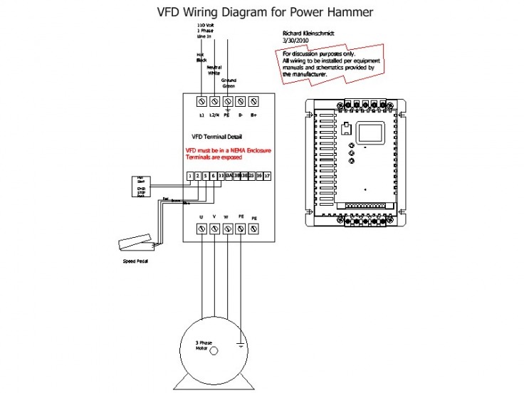
VFD Wiring Diagram SD Metalworks
Based on the difference between these two values, the required pump flow is calculated using PID control logic. Since pump flow is dependent on pump motor speed (this function is given by pump manufacturer), required flow can be achieved by adjusting a motor speed via VFD which is controlled by PLC. The wiring diagram of VFD outgoing inside MCC.

Vfd Panel Wiring Diagram Free Wiring Diagram
A VFD schematic diagram is a visual representation of the components needed to create a VFD system. It is important to understand how VFDs work and how to properly assemble them in order to get the best performance out of your industrial automation system. A typical VFD schematic diagram will include a controller, a power source, and the motor.
Beginner VFD Wiring
8.1.3 Typical Wiring Diagrams 9-6 Contents Vertical Bypass/Non Bypass Panel. Figure 3.14: Non Bypass Panel Conduit Entry Diagram 3-16 Figure 3.15: P2 Panel 3-17 Figure 3.16: P3 Panel 3-17 Figure 3.17: P4 Panel 3-18 Figure 3.18: P5 Panel 3-19 Figure 3.19: Control Terminals Location 3-26
vfd wiring diagrams
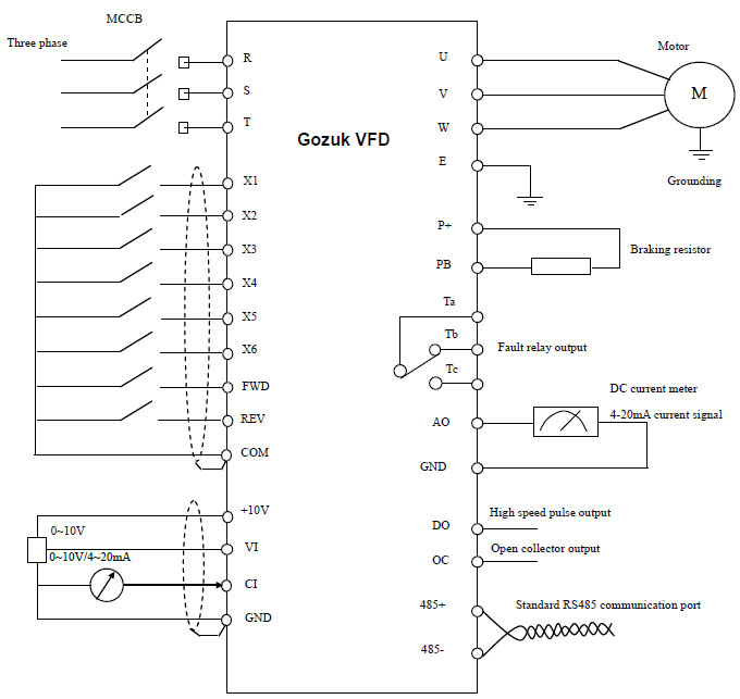
1. Main circuit wiring The VFD main circuit terminals shown as below Figure. (1) The VFD's three phase AC input terminals (r/l1, s/l2, t/l3) The power line's input terminals connect to 3 phase AC power through line protection or leakage protection breaker, it does not need to consider the connection of phase sequence.
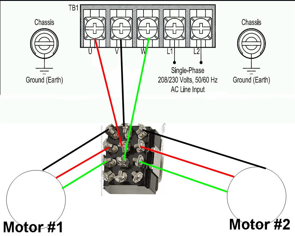
1 vfd 2 motors
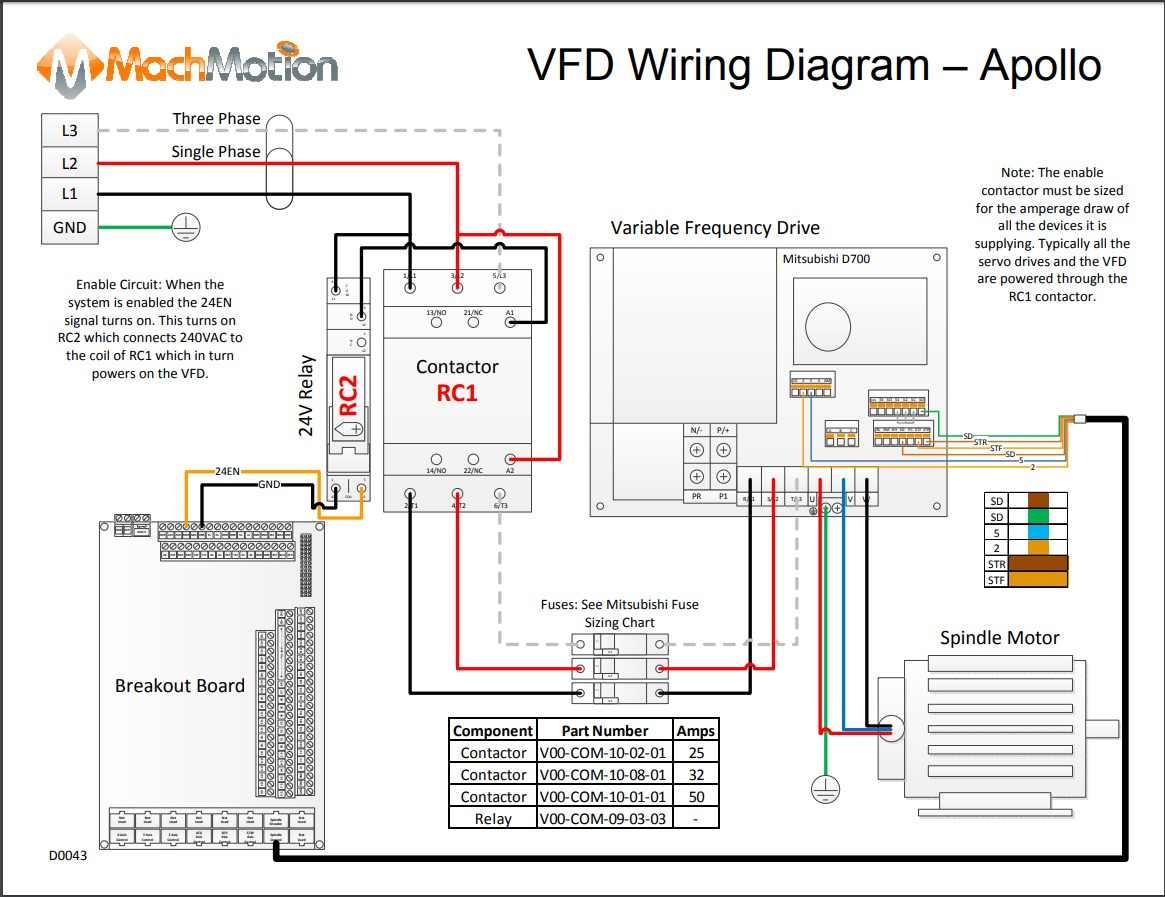
Title: Visio-D0043 - VFD Wiring Diagram - Apollo.vsd Author: mark Created Date: 12/26/2013 2:19:17 PM

Vfd Panel Wiring Diagram Pdf
When downloading a VFD Panel Wiring Diagram PDF, make sure to look for one that has been created by an experienced electrician. This will ensure that all of the instructions are accurate and easy to understand. Additionally, make sure to double-check the diagram for compatibility with the type of control system you're using. Different systems.
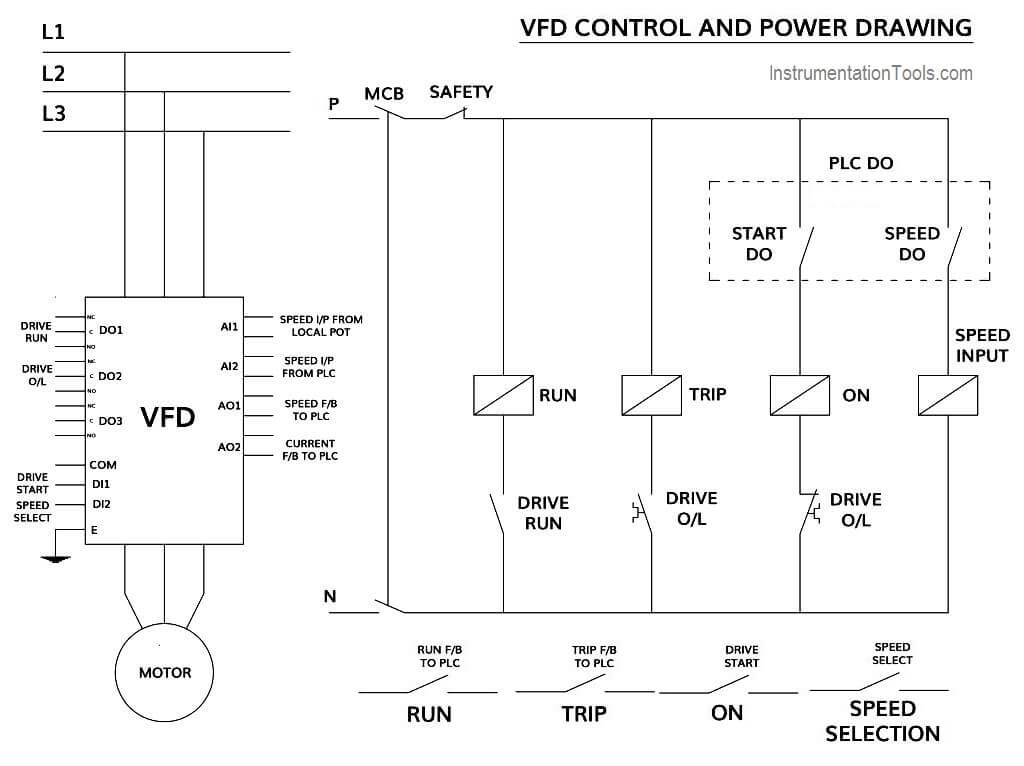
How to Control VFD with PLC using Ladder Logic InstrumentationTools
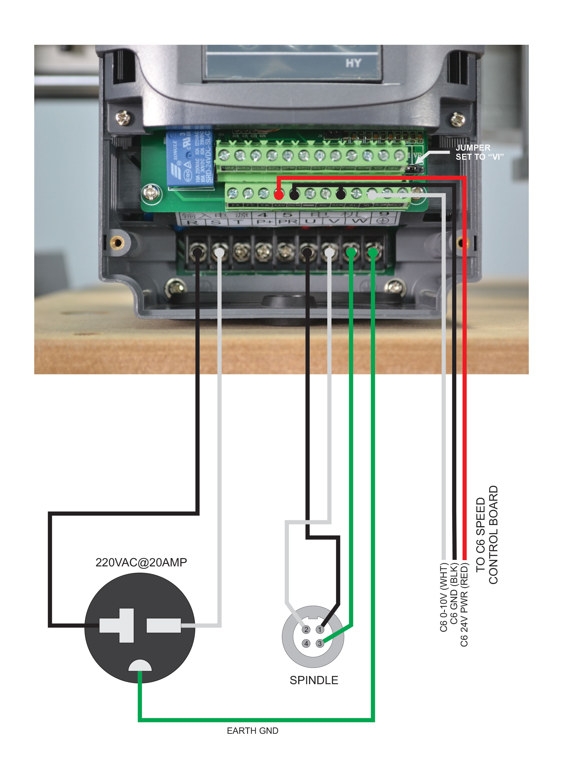
STEP 1: Make sure everything is correctly sized and accounted for Look at the nameplate on your motor and make sure your VFD is sized correctly. How many full load amps does your motor draw? Is your VFD rated for the amount of amps your motor draws? How many volts does your motor require (460V or 230V)?

Wiring Diagram For Vsd
Home Wiring Diagram how to wire plc to vfd How To Wire Plc Vfd By Wiring Work | August 23, 2022 0 Comment The Programmable Logic Controller (PLC) and Variable Frequency Drive (VFD) are two of the most important components for a successful automation project.

Vfd Panel Wiring Diagram Free Wiring Diagram
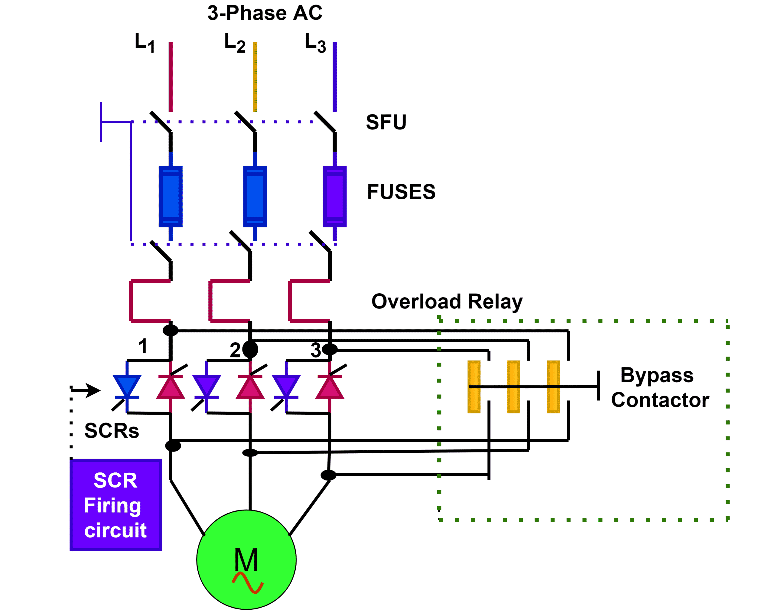
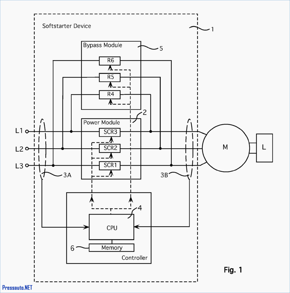
Potential Faults and Solutions 1. Introduction to VFDs For many years, the major challenge to some motor-driven applications was the inability to control their speed. However, the advent of reliable power electronics made it possible to control the speed of motors using variable-frequency drivers. VFDs are widely used in many applications nowadays.
Vfd Piping Schematic Symbol Wiring Diagrams Hubs Vfd Wiring Diagram Wiring Diagram
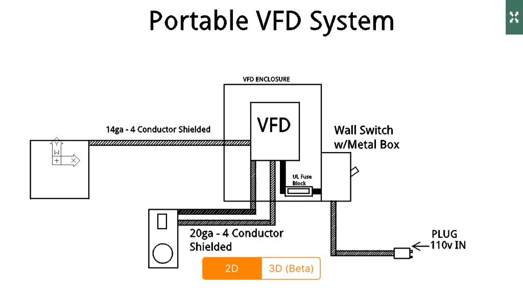
Download scientific diagram | VFD wiring diagram showing power in, power out, and control device connections. Readers should consult and follow the VFD and motor manufacturers' wiring diagrams and.

VFD wiring diagram showing power in, power out, and control device... Download Scientific Diagram
DIN1: DIGITAL INPUT 1 DIN2: DIGITAL INPUT 2 DIN3: DIGITAL INPUT 3 CM: COMMON FOR DI1 - DI3 24V OUT: 24V AUXILLARY VOLTAGE GND: I/O GROUND DIN4: DIGITAL INPUT 4 DIN5: DIGITAL INPUT 5 DIN6: DIGITAL INPUT 6 CM: COMMON FOR DI4 - DI6 AO+: ANALOG SIGNAL +OUT AO-/GND: ANALOG OUTPUT COMMON +24VIN: 24V AUXILLARY INPUT VOLTAGE RS485: NEGATIVE RS485: POSITIVE