Mosquito Swatter Bat Circuit Circuit Diagram Centre
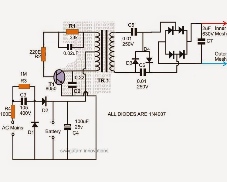
Building a mosquito zapper circuit diagram involves connecting a power source, such as a battery, to a transformer. This changes the voltage to a higher level, which is then passed through a capacitor, resistor, and coil. The capacitor stores energy which is released as an electric shock when the mosquito touches the metal grid.

Mosquito Repeller Circuit Diagram
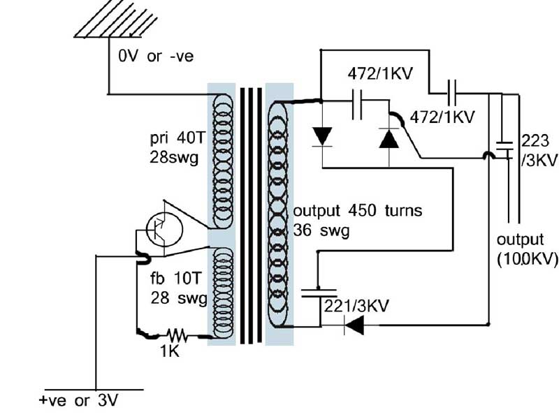
Mosquito Killer Circuit Diagram: This is the high voltage mosquito killer circuit diagram which only consists of capacitors and diodes. This is basically a voltage multiplier circuit which gives a high voltage of around 1860 volts. As a general rule of thumb, multiply the total number of capacitors with the voltage and then divide it by 2 and.
Mosquito Killer Circuit with Window Trap Homemade Circuit Projects
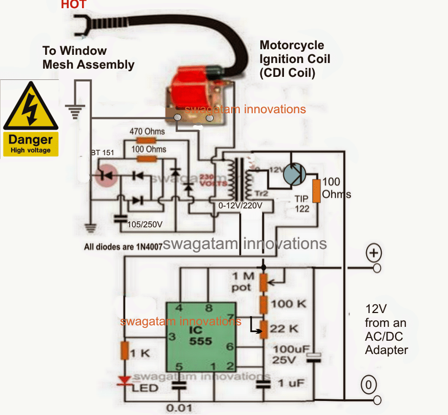
There are three stages to a bug zapper circuit: Charging circuit stage Transistor stage Voltage booster stage Charging Circuit Stage The charging circuit stage comprises a capacitive power supply that rectifies the voltage by adjusting the current from the source.
ELECTRONIC MOSQUITO REPELLENT CIRCUIT USING TINKER CAD project
Circuit Diagram "New copper coin electrodes for my parasite zapper, these are really neat and can be modified to be able to be secured Velcro strap for parasite zapping this is one of a number of pictures I've uploaded to SkyDrive."

What You Need To Know About Bug Zapper Circuit? RAYPCB
required Zapper voltage is from 600 to 1200 volts ac. Figure 1.1 is the general circuit d iagram of the Zapper. It was concepted from the many on the net to be sho wn having four simple sections.

Electric Mosquito Racket Teardown — TWorks
the required Zapper voltage is from 600 to 1200 volts ac. Figure 1.1 is the general circuit diagram of the Zapper. The Zapper Circuit functions by the following principles; when the battery power is switched on, the RC oscillator produces a waveform like a square wave which switches transistor T1 On and Off and as such

Making a Parasite Zapper Circuit with Steven Chiverton Circuit
Mosquito Zapper Circuit Diagram and Theory of Operation Uploaded by crecosiro Learn about a theory of operation of a mosquito zapper circuit Copyright: © All Rights Reserved Available Formats Download as DOCX, PDF, TXT or read online from Scribd Flag for inappropriate content Download now of 3

Electronic Mosquito Racket Circuit Diagram
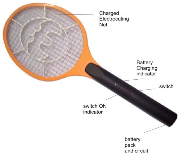
How To Protection Working of Electric Mosquito Killer Racket / Fly Swatter Bat Electrical Technology 0 6 minutes read Circuit Diagram and Working of Mosquito Killer Racket, Fly Swatter Bat, Bug Zapper etc. Mosquitos are small but very annoying little insects that are present in every corner of the world.

Diy Bug Zapper Circuit
19 For the purpose of learning, I have tear down a small mosquito zapper racket. I am now trying to understand how the circuit is working (which goal is to produce high voltage). (yellow = resistor, black = transistor, red = led, gray = diode, blue = capacitor, brown = switch or wire) Battery is on the left, high voltage output on the right.

Mosquito Racket Circuit Diagram
Pdf design and construction of a tripler circuit for mosquitor zapper mosquito aj engineering high voltage diagram facebook help with electronic repellent all about circuits how bug zappers work howstuffworks repeller under repository 25390 next gr making parasite homemade projects 2 swatter bat explained index 123 electrical equipment seekic com deals 57 off www ingeniovirtual efy s.
Mosquito Bat Circuit Working Principle Pest Control Diagram
Contexts in source publication. Context 1.. main body resistance of most bugs and mosquitoes fall within the range of 0.70 -0.75Ω and the required Zapper voltage is from 600 to 1200 volts ac.
Mosquito Zapper Circuit Diagram and Theory of Operation
The main body resistance of most bugs and mosquitoes fall within the range of 0.70 - 0.75 Ω [3] and the required Zapper voltage is from 600 to 1200 volts ac. Figure 1.1 is the general circuit diagram of the Zapper. The Zapper Circuit functions by the following principles; when the battery power is switched on, the

Mosquito Killer Light Circuit PeepsBurgh
Bug Zapper Wiring DiagramBug Zapper Wiring HarnessBug Zapper Service ManualBug Zapper User ManualBug Zapper Manual BooksBug Zapper Schematic Diagram

What You Need To Know About Bug Zapper Circuit? RAYPCB
6. Activity points. 1,065. Hello, I'm in the process of designing a mosquito zapper. I tried to gather as much details as I can about their theory of operation and popular circuits. I have also a bunch of them here and I have already opened some to take a look at their inner workings. Well, as an embedded designer, I do not get involved a lot.

Electric Mosquito Killer Racket Circuit Diagram
The moment a mosquito or any bug comes in contact with the meshes, the stored high voltage in the capacitor discharges violently through the body of the entangled bug creating a big spark and electrocuting it instantly. Ever want to build your own mosquito killing device?

Mosquito Killer Bat Circuit Working Explanation Electrothinks
Mosquito Zapper Circuit Diagram A mosquito zapper is a device that uses electricity to kill mosquitoes. It typically consists of a high-voltage transformer, a metal grid, and a light source. When a mosquito flies into the grid, it completes the circuit and receives a fatal electric shock. Mosquito zappers are a popular way to control mosquito.